Vectaire WHHR Midi Compatible Replacement Filter Set - G3
£14.50
MVHR unit guide
MVHRVectaire
The Vectaire Midi is a wall, cupboard or loft mounted MVHR unit for homes up to 170 m², with summer bypass, frost-stat and up to 94% heat exchange efficiency.
Buy replacement filters for WHHR-Midi-BY, Midi-BY-LCD, Midi-BY-AT-LCD
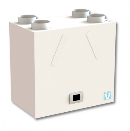
The Vectaire Midi is a vertical whole-house mechanical ventilation unit with heat recovery (MVHR). The range covered here comprises the WHHR-Midi-BY, the Midi-BY-LCD with an integral LCD screen, and the Midi-BY-AT-LCD, which adds acoustic attenuation. Each is designed for homes up to 170 m² and is installed on a wall, in a cupboard or in a loft, always in the vertical position.
Two fans do the work: one extracts stale, damp air from the kitchen, utility room and bathrooms, while the other supplies fresh air to living areas and bedrooms. Both airflows pass through a counter flow heat exchanger, so heat from the outgoing air warms the incoming air without the two streams mixing. The unit is built to run continuously and should only be switched off for maintenance or filter replacement.
The casing is epoxy-painted steel with a thermo-acoustic lining, and the fans are EC brushless motors whose trickle, boost and purge speeds are set independently on each motor during commissioning. An automatic summer bypass lets both airflows avoid the heat exchanger, and a frost-stat reduces intake fan speed as the outside temperature falls. Humidistat versions are supplied either left or right handed, while the other versions have universal handing. The Midi-BY-AT-LCD is lined with Class O fire resistant acoustic foam to lower noise further.
Air passes through disposable filters on the front panel. The standard grade is G3, the filter size is 185 x 360 mm, and filters are available in G3, G4 and M5 grades. Cleaning or replacing the filters is part of the routine maintenance, and the heat exchanger itself should be cleaned annually.
£14.50
£16.00
£18.75
The unit uses a 230 V supply and has rotating parts, so the mains electrical supply must be disconnected before any cleaning or maintenance.
Take the filter covers off the front panel to expose the filters.
Pull the tabs to slide each filter out of its slot.
Clean the filters carefully with a vacuum cleaner. If they are due for replacement (annually or after a maximum of 3 cleaning cycles), fit new ones of the 185 x 360 mm size instead.
Slide the filters back into their slots and refit the filter covers.
On versions with the LCD screen, use the user screen to reset the filter saturation level after the filters have been changed.
Vectaire and all other manufacturer and product names, model numbers and part numbers on this page are the property of their respective owners and are used for identification only. MVHR.shop is an independent supplier of compatible filters. We are not affiliated with, endorsed by, sponsored by or approved by Vectaire or any other manufacturer named on this page.
This page is our own summary, written from documents published by the manufacturer (such as installation, user and product literature). We do not own the underlying information: all rights in the original documents, specifications, drawings and data remain with the manufacturer, and nothing here is intended to replace them.
The information is provided in good faith for general guidance only. Manufacturers revise their products and documents, specifications can differ between versions and production batches, and errors or omissions may exist, so we cannot guarantee that it is accurate, complete or up to date. Always check the manufacturer's current documentation and the rating label on your own unit before relying on any figure or part number. Nothing on this page is installation, electrical, commissioning or safety advice; work on ventilation equipment must be carried out by a competent person in line with the manufacturer's instructions and current regulations. To the fullest extent permitted by law we accept no liability for loss arising from reliance on this page. Nothing in this notice limits any liability that cannot be limited by law.
Links to other websites, including manufacturers' sites and documents, are provided for convenience only. We do not control, endorse or accept responsibility for their content, availability or privacy practices, and they may change or be removed without notice.
If you believe something on this page is wrong, or you are a rights holder with a concern, please contact us and we will review it promptly.
| Part no. | Description |
|---|---|
WHHR-Midi/BY | Midi with bypass, universal handing (also printed WHHR-Midi-BY) |
WHHR-Midi/LBYH | Midi with bypass, left drain, humidistat |
WHHR-Midi/RBYH | Midi with bypass, right drain, humidistat |
Midi-BY+LCD | Midi with bypass, universal handing, integral LCD (also printed Midi-BY-LCD) |
Midi-BY+LCDLH | Midi with bypass, integral LCD, left drain, humidistat |
Midi-BY+LCDRH | Midi with bypass, integral LCD, right drain, humidistat |
Midi BY-AT+LCD | Midi with bypass, acoustic attenuation, universal handing, integral LCD (also printed Midi-BY-AT-LCD) |
Midi BYAT+LCDLH | Midi with bypass, acoustic attenuation, left drain, humidistat, integral LCD |
Midi BYAT+LCDRH | Midi with bypass, acoustic attenuation, right drain, humidistat, integral LCD |
WHHR Midi L | WHHR Midi, left drain |
WHHR Midi R | WHHR Midi, right drain |
WHHR Midi HL | WHHR Midi with humidistat, left drain |
WHHR Midi HR | WHHR Midi with humidistat, right drain |
WHHR Midi BL | WHHR Midi with bypass, left drain |
WHHR Midi BR | WHHR Midi with bypass, right drain |
WHHR Midi BLH | WHHR Midi with bypass and humidistat |
| Part no. | Description |
|---|---|
LCD-DISPLAY | Remote LCD commissioning unit for the Midi range |
DRH240 | Dynamic remote humidistat, 230V switched live boost trigger |
PIRFF | Passive infra red sensor, 230V switched live boost trigger |
THM | Thermostat, 230V switched live boost trigger |
| Task | How often |
|---|---|
| Clean the filters Vacuum carefully. Work should be done by a suitably qualified person with the mains supply disconnected. | Regularly; frequency varies with the installation environment |
| Replace the filters Reset the filter saturation level on LCD versions. | Annually or after a maximum of 3 cleaning cycles |
| Clean the heat exchanger Vacuum the faces lightly. Never use water or other fluids. The exchanger may hold water if removed in cold weather, so have a plastic bowl ready. | Annually |
| Maintenance access check Keep sufficient access for safe maintenance or removal. | Annually (recommended) |
| Fan speed | Airflow (l/s) | Total power (W) |
|---|---|---|
| 100% | 101 | 120 |
| 80% | 79 | 69 |
| 60% | 58 | 31 |
| 40% | 36 | 11 |
| 20% | 14 | 2.2 |
| Fan speed | Airflow (l/s) | Midi (dB(A)) | Midi-BY-AT (dB(A)) |
|---|---|---|---|
| 100% | 101 | 29.7 | 25.3 |
| 80% | 79 | 27.2 | 23.4 |
| 60% | 58 | 24.4 | 18.7 |
| 40% | 36 | 21.6 | 15.8 |
| 20% | 14 | 19.2 | 14.4 |
Hemispherical free field propagation at a distance of 3 m from the unit.
| Path | 63 Hz | 125 Hz | 250 Hz | 500 Hz | 1k Hz | 2k Hz | 4k Hz | 8k Hz |
|---|---|---|---|---|---|---|---|---|
| Extract (Midi and Midi-BY-AT) | 65 | 65 | 63 | 63 | 59 | 58 | 57 | 54 |
| Supply (Midi and Midi-BY-AT) | 70 | 70 | 68 | 68 | 64 | 63 | 62 | 59 |
| Breakout (Midi) | 55 | 57 | 53 | 42 | 34 | 31 | 24 | 17 |
| Breakout (Midi-BY-AT) | 53 | 55 | 48 | 35 | 26 | 23 | 17 | 11 |
| Exhaust terminal configuration | 2009 airflow (l/s) | 2009 SFP (W/l/s) | 2009 heat exchange efficiency | 2012 airflow (l/s) | 2012 SFP (W/l/s) | 2012 heat exchange efficiency |
|---|---|---|---|---|---|---|
| Kitchen + 1 additional wet room | 15 | 0.50 | 94% | 21 | 0.51 | 93% |
| Kitchen + 2 additional wet rooms | 21 | 0.50 | 93% | 29 | 0.61 | 91% |
| Kitchen + 3 additional wet rooms | 27 | 0.55 | 92% | 37 | 0.75 | 90% |
| Kitchen + 4 additional wet rooms | 33 | 0.65 | 91% | 45 | 0.92 | 89% |
| Kitchen + 5 additional wet rooms | 39 | 0.76 | 89% | - | - | - |
| Kitchen + 6 additional wet rooms | 45 | 0.88 | 89% | - | - | - |
Using rigid ducting only. Figures at minimum flow rate conditions.
| Version | Built-in humidistat | Size W x H x D (mm) | Weight (kg) | Enhanced acoustic attenuation |
|---|---|---|---|---|
| Standard (S) | No | 600 x 564 x 382 | 24 | No |
| Humidistat (H) | Yes | 600 x 564 x 382 | 24 | No |
| Acoustic attenuation (AT) | On request | 648 x 595 x 395 | 29 | Yes |
Universal handing applies to the non-humidistat versions.
For a BMS (remote motor shut-off), CO2 detector, home automation system or external pre-heater
Listed among the factory-set control options
Likely cause: Filters have reached their saturation level
What to do: Clean or replace the filters, then reset the filter saturation level on the LCD user screen.
Likely cause: An incorrect passcode was entered 5 times in a row
What to do: The system locks automatically for one hour. Commissioning options are for the installer and need the Commissioning Access Code.
Likely cause: The unit may sometimes produce condensation
What to do: Make sure the condensate drain is fitted, trapped, insulated where needed and falls continuously to the household drainage.
Both airflows can bypass the heat exchanger automatically when internal and external temperatures sit between adjustable setpoints, so warm weather does not add unwanted heat to incoming air.
The intake fan speed is reduced in proportion as the temperature falls, which limits cold air entering the home. It acts when the outside temperature is between +8°C and -3°C.
Trickle, boost and purge speeds are set separately for the supply and extract motors at commissioning, so the airflow can be matched to the design of the home.
Boost can be triggered by a light switch (double pole where more than one is used), a DRH240 remote humidistat, a PIRFF passive infra red sensor, a THM thermostat, or a remote switch or pull cord.
The unit counts running time and power outages, and the figures can be downloaded using a QR code.
Humidistat versions run at a pre-determined boost speed when the factory-set humidity trip point is reached, then return to trickle speed once humidity falls below it. These versions are left or right handed.
The LCD shows fan speeds, inside and outside temperatures, humidity, bypass status, error and service notices and filter saturation level, and lets the user reset filter saturation after a filter change.
The casing is lined with Class O fire resistant acoustic foam, giving breakout sound pressure of 25.3 dB(A) at 3 m at full speed against 29.7 dB(A) for the standard Midi.
Factory-set options include a holiday mode (default 50% of trickle speed) and 0-10V connections for a BMS, CO2 detector, home automation system or external pre-heater.
The Midi must be installed vertically, normally in a cupboard, loft or ceiling void, in clean, dry conditions. It is not suitable for the exterior of a dwelling and must not be installed where there is excessive oil or grease, where flammable or corrosive gases, liquids or vapours are present, in ambient temperatures above 40°C or below 0°C, or in areas of excessive humidity. Where possible it should not be placed directly above a bedroom or living room. Allow at least 150 mm of clearance on each side of the cabinet for access to the motors, and arrange access for safe maintenance, which is recommended annually.
Mounting uses a wall bracket and a lower safety bracket: mark a level line about 40 mm below the position of the unit's top face (excluding the duct ports), use the bracket as a template for the five fixing holes, fit the bracket with its interlocking side at the top, hang the unit on it and fix the safety bracket. The fixings supplied are for solid walls. The four 125 mm spigots are marked for the supply and exhaust ducts. Insulate all ducts in an unheated space and only the cold ducts (supply from outside and extract to outside) in a heated space; fit fire dampers where ducting passes through a fire partition; and fit a safety grille to any spigot not connected to ducting. The ductwork installer should tick the as installed left or right handed box on the label on top of the unit.
A condensate drain must be fitted. Connect it to the left or right hand outlet that matches the duct layout, always on the atmosphere side of the unit, cap the unused outlet, and fit a wet or dry trap with a continuous fall to the household drainage. Insulate any run through an unheated space. Installation, electrical connection and commissioning must be carried out by a suitably qualified and competent person, in line with current wiring regulations, using a triple pole isolation switch with at least 3 mm contact separation when the switched live is used. With the control board panel removed, 230 V live connections are accessible.
 International Customers
It looks like you're outside the UK - unfortunately we can't ship internationally through our website, but we can provide a shipping quote if you contact us.
Buying for Individual or Business use?
This setting affects VAT inclusion, Pro Forma Invoices and Pull Tabs configuration.
Please note that this does not affect item prices.
Set Your Delivery Location
Let us know where you're ordering to and we'll be able to show delivery estimates for your area.