

Nuaire MRXBOX95-WH1 (MRXBOX-ECO3) Compatible Replacement Filter Set - G3
£18.00
MVHR unit guide
MVHRNuaire
Wall-mounted Nuaire MVHR unit with two independent fans and four 150 mm spigots, stated to recover up to 95% of the heat normally lost from extract air.
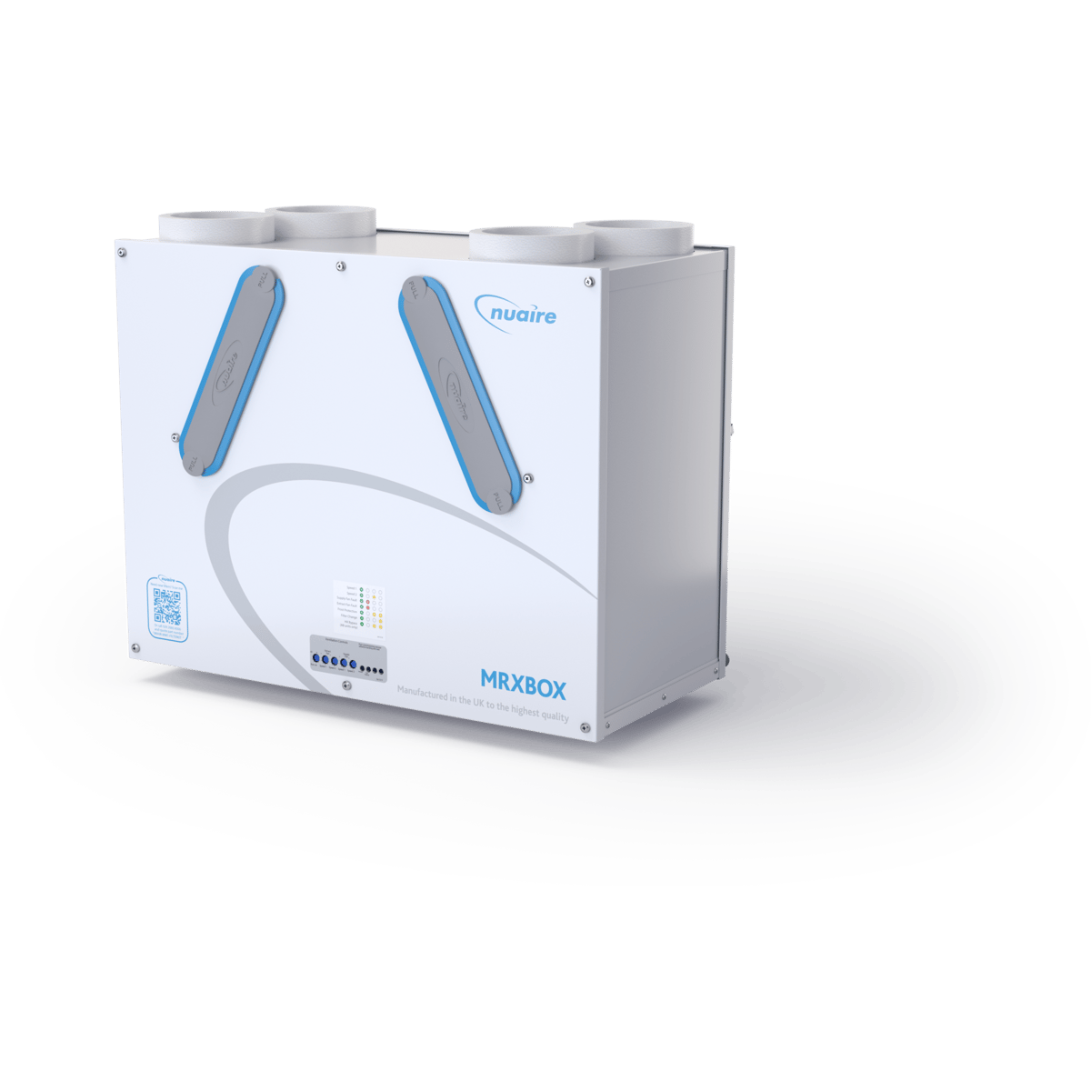
The Nuaire MRXBOX95-WH1 is a wall-mounted mechanical ventilation unit with heat recovery, part of Nuaire’s WH1 range. It extracts moist air from wet rooms such as the kitchen, bathroom, en-suite and a utility room with a sink, and supplies filtered fresh air to habitable rooms such as bedrooms and the lounge. A heat exchanger passes heat from the outgoing extract air to the incoming air, and the manufacturer states that it can recover up to 95% of the heat that would otherwise be wasted. The system is designed to run continuously, so the unit must stay switched on at all times; turning it off can cause long-term damage to the unit and the building fabric.
Inside the casing are two independent fans, one for supply and one for extract, each with speed control for background and boost ventilation. Nuaire describes the WH1 system as designed for medium to large new build properties. Air enters and leaves through four 150 mm spigots on the top of the casing, and the unit hangs on an interlocking wall bracket. It needs a solid wall, or a stud partition backed by 25 mm MDF, and it can also be mounted in a loft space on an anti-vibration tray. Condensation from the heat exchanger is piped away through a condensate connection that must discharge through a trap or an equivalent airlock.
The installation manual covers four versions: the standard MRXBOX95-WH1, the opposite-hand MRXBOX95-WH1-OH, and the MRXBOX95AB-WH1 and MRXBOX95AB-WH1-OH, which add an integral automatic summer bypass and a humidity sensor with an adjustable set point. On the non-AB versions, the supply fan instead reduces to a trickle speed in excessive outside temperatures. An optional speed 3 switch overrides both speeds to run the fans at maximum airflow.
The two filters sit behind removable covers on the front panel. They are G3 filters measuring 188 x 413 mm, inspected after six months and replaced every 12 to 18 months; filters of this size are also available in G4 and M5 grades. The heat exchanger should be inspected every five years, and the five-year warranty is conditional on planned maintenance being carried out.
£18.00
£19.50
£23.00
Electrically isolate the unit, the switched live and any Nuaire control from the mains and switched live supply, then allow at least two minutes for the fans to come to rest before removing any panel.
Take hold of the circular tab at each end of the filter covers on the front panel and pull the covers out.
Pull the removal loop on the front edge of each filter (the black tab on the visible end) to extract it from the unit.
Check each filter. Return it if it is serviceable, or replace it; the filters are inspected after 6 months and replaced every 12 to 18 months.
Clean a reusable filter with a vacuum cleaner, or fit a new filter (G3, 188 x 413 mm).
Slide the filters back into the unit.
Replace the two filter covers and secure the tabs, then restore the power supply.
 MVHRVent-Axia Sentinel Kinetic High Flow Specs, Manual, Fault Codes & Filters
 MVHRVent-Axia Sentinel Kinetic V, B and BH Specs, Manual, Fault Codes & Filters
 MVHRVectaire WHHR-Midi-BY, Midi-BY-LCD, Midi-BY-AT-LCD Specs, Manual, Fault Codes & Filters
 MVHRVent-Axia Sentinel Kinetic Plus B Specs, Manual, Fault Codes & Filters
Nuaire and all other manufacturer and product names, model numbers and part numbers on this page are the property of their respective owners and are used for identification only. MVHR.shop is an independent supplier of compatible filters. We are not affiliated with, endorsed by, sponsored by or approved by Nuaire or any other manufacturer named on this page.
This page is our own summary, written from documents published by the manufacturer (such as installation, user and product literature). We do not own the underlying information: all rights in the original documents, specifications, drawings and data remain with the manufacturer, and nothing here is intended to replace them.
The information is provided in good faith for general guidance only. Manufacturers revise their products and documents, specifications can differ between versions and production batches, and errors or omissions may exist, so we cannot guarantee that it is accurate, complete or up to date. Always check the manufacturer's current documentation and the rating label on your own unit before relying on any figure or part number. Nothing on this page is installation, electrical, commissioning or safety advice; work on ventilation equipment must be carried out by a competent person in line with the manufacturer's instructions and current regulations. To the fullest extent permitted by law we accept no liability for loss arising from reliance on this page. Nothing in this notice limits any liability that cannot be limited by law.
Links to other websites, including manufacturers' sites and documents, are provided for convenience only. We do not control, endorse or accept responsibility for their content, availability or privacy practices, and they may change or be removed without notice.
If you believe something on this page is wrong, or you are a rights holder with a concern, please contact us and we will review it promptly.
| Part no. | Description | Notes |
|---|---|---|
MRXBOX95-WH1 | Wall mounted MVHR unit, standard unit | Standard handing; no integral automatic bypass |
MRXBOX95-WH1-OH | Wall mounted MVHR unit, opposite hand | Opposite handing; no integral automatic bypass |
MRXBOX95AB-WH1 | Wall mounted MVHR unit with integral automatic HX bypass, standard unit | Standard handing; includes humidity adjustment |
MRXBOX95AB-WH1-OH | Wall mounted MVHR unit with integral automatic HX bypass, opposite hand | Opposite handing; includes humidity adjustment |
| Part no. | Description | Notes |
|---|---|---|
778651 | Replacement filters for the MRXBOX95-WH1 | G3 grade, 188 x 413 mm; filters of this size are available in G3, G4 and M5 |
| Part no. | Description | Notes |
|---|---|---|
MRXBOX95-RFI | Remote fail indicator for the WH1 units | Optional; connects to the fail terminals |
MRXBOX-JB | Junction box for connecting more than one Ecosmart sensor | Installation instructions in leaflet 671700 |
| Part no. | Description | Notes |
|---|---|---|
SIL-WH1 | Silencer for MRXBOX95(AB)-WH1 units | Four airflow chambers; part of the acoustic solution system |
FF-WH1 | First fix plenum chamber for MRXBOX95(AB)-WH1 units | Four 204 x 60 mm rectangular spigots (two each side); four hanging brackets |
AV-WH1 | Anti-vibration tray assembly for loft space mounting of the WH1 units | Used with the angle brackets on an MDF false wall; without the angle brackets on a tank stand |
MVHR-DRAIN | Condensate drain take-off recommended as the primary condensate connection | Uninsulated drain pipe with minimum 5° fall to the soil and vent pipe |
PVC604 | Louvre grille for 150 mm ducting, shown for intake and exhaust in the AB-WH1 ducting arrangement | |
PVC501 | Air brick for 204 x 60 mm rectangular ducting, shown for intake and exhaust in the AB-WH1 ducting arrangement | |
VS150 | Ceiling air valve for 150 mm ducting, shown for supply and extract in the AB-WH1 ducting arrangement | |
VS125 | Ceiling air valve shown for supply and extract in the AB-WH1 rectangular ducting arrangement |
| Task | How often |
|---|---|
| Inspect the filters Two G3 filters accessed from the front panel | After 6 months |
| Replace the filters Depending on the environment, filters may be cleaned with a vacuum cleaner or replaced | Every 12 to 18 months |
| Professional inspection of the unit Includes the filters, heat exchanger and motors | Annually |
| Inspect the heat exchanger Check generally for damage and security of components, then refit the cover | Every 5 years |
| Room | Minimum high rate |
|---|---|
| Kitchen | 13 l/s |
| Utility room | 8 l/s |
| Bathroom | 8 l/s |
| Sanitary accommodation | 6 l/s |
Minimum low rate: total extract rate should be at least the whole dwelling ventilation rate given in the next table.
| Number of bedrooms | Whole dwelling ventilation rate |
|---|---|
| 1 | 13 l/s |
| 2 | 17 l/s |
| 3 | 21 l/s |
| 4 | 25 l/s |
| 5 | 29 l/s |
The minimum ventilation rate should also be not less than 0.3 l/s per m² of internal floor area, counting all floors. Based on two occupants in the main bedroom and one in each other bedroom; add 4 l/s per occupant for higher occupancy.
| Model | Handing | Bypass |
|---|---|---|
| MRXBOX95-WH1 | Standard | Non-AB (thermal bypass behaviour) |
| MRXBOX95-WH1-OH | Opposite hand | Non-AB (thermal bypass behaviour) |
| MRXBOX95AB-WH1 | Standard | Integral automatic HX bypass |
| MRXBOX95AB-WH1-OH | Opposite hand | Integral automatic HX bypass |
Likely cause: A fault on the supply fan is being indicated on the front panel
What to do: Isolate the unit before any work and have a competent person examine it. Equipment with a suspected failure should be taken out of service until a competent person can repair or examine it.
Likely cause: A fault on the extract fan is being indicated on the front panel
What to do: Isolate the unit before any work and have a competent person examine it. Equipment with a suspected failure should be taken out of service until a competent person can repair or examine it.
Likely cause: The filters are due for attention
What to do: Isolate the unit, then inspect and clean or replace the two G3 filters as described in the filter change steps.
Likely cause: The unit has not been installed true in all three dimensions
What to do: Re-fit the unit so that it is level in all three dimensions, using a competent installer.
Likely cause: Thermal bypass behaviour: the supply fan reduces automatically in excessive outside temperatures to help prevent overheating
What to do: Use additional ventilation measures such as open windows or trickle vents (if fitted).
Likely cause: Radio frequency interference
What to do: No action: this is normal and the speed returns to normal once the interference has subsided.
Likely cause: Unit switched off, or controls and valves adjusted after commissioning
What to do: Keep the unit switched on at all times and do not adjust the commissioned settings; contact a competent installer if the problem continues.
Separate supply and extract fans each have their own speed control, so background and boost flow can be set for each side of the system during commissioning.
The heat exchanger transfers heat from the extract air to the incoming air; the manufacturer states it can recover up to 95% of the heat normally wasted.
A two-part bracket is fixed to the wall and to the rear of the unit, and the unit simply interlocks over the wall-mounted part. The unit must be level in all three dimensions to avoid drip tray overflow.
The OH versions mirror the airflow arrangement of the standard units, so the spigot layout can be matched to the duct runs in the dwelling.
An optional speed 3 switch overrides both speed 1 and speed 2 and drives the fans to maximum airflow, for example from a kitchen switch.
Both G3 filters are removed from the front by pulling off two filter covers, then drawing each filter out by its loop, with no need to take the unit off the wall.
A wax actuator opens the bypass damper automatically so air can pass around the heat exchanger and deliver fresh filtered air in warmer months.
A sensor in the extract airflow boosts the unit to the commissioned boost speed when humidity exceeds an adjustable set point on the front of the unit. It should not be relied on alone, so a switch local to the wet rooms is also used.
In excessive outside temperatures the supply fan reduces automatically to a trickle speed to help prevent overheating, so additional ventilation such as open windows or trickle vents may be needed.
The unit is installed indoors on a solid wall, away from direct sources of frost, heat, water spray or moisture generation, using the supplied interlocking bracket; a gypsum block or ordinary stud wall is not sufficient unless a 25 mm minimum MDF panel is solidly fixed behind the board, extending over at least three studs at no more than 400 mm centres and ideally from floor to ceiling (minimum 2 m). Allow at least 430 mm clear space in front of the MRXBOX95-WH1 for cover removal and filter changes, and install the unit level in all three dimensions.
Use rigid 150 mm circular or 204 x 60 mm rectangular ducting where possible, insulate the intake and exhaust ducts, keep intake terminals at least 300 mm from a gas boiler balanced flue as a guide, and pipe the condensate through a filled U-trap or equivalent airlock. Remove the protective film from the filters before commissioning, and commission with a calibrated moving vane anemometer and hood.
Installation must be carried out by competent personnel, and the electrical connection by a qualified electrician. Isolate the unit, switched live and Nuaire control from the mains before any work.
 International Customers
It looks like you're outside the UK - unfortunately we can't ship internationally through our website, but we can provide a shipping quote if you contact us.
Buying for Individual or Business use?
This setting affects VAT inclusion, Pro Forma Invoices and Pull Tabs configuration.
Please note that this does not affect item prices.
Set Your Delivery Location
Let us know where you're ordering to and we'll be able to show delivery estimates for your area.