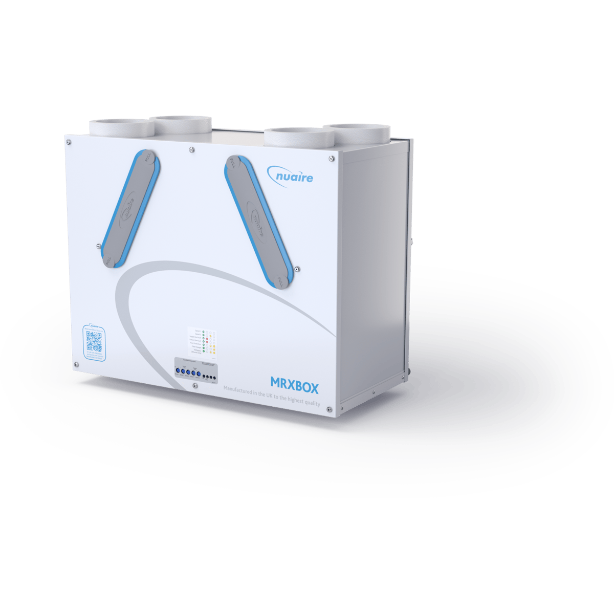

Vent-Axia Sentinel Kinetic F & FH Compatible Replacement Filter Set - G3
409764
£14.50
MVHR unit guide
MVHRVent-Axia
The Vent-Axia Sentinel Kinetic F and FH are wall-mounted MVHR units; the FH adds a summer bypass and an integral humidity sensor.

The Sentinel Kinetic F and FH are wall-mounted mechanical ventilation with heat recovery (MVHR) units made by Vent-Axia. They run continuously, drawing stale, moist air from bathrooms, toilets and kitchens and passing it through a heat exchanger that transfers heat to the fresh air supplied to bedrooms and living areas. They are intended for houses and similar dwellings under the 2010 edition of Approved Document F. For the FH, the ErP product fiche gives a thermal efficiency of 90% and an energy class of SEC A+.
The FH has a summer bypass, a damper that sends outdoor air around the heat exchanger when the house is warmer than the indoor temperature set on the controller and the air outside is cooler, and an integral humidity sensor that raises fan speed as relative humidity rises. It is made as a right-hand unit (408167) and a left-hand unit (408169), each also available with an acoustic enclosure, an acoustic top box or both. The casing is 550 mm high, 555 mm wide and 350 mm deep, weighs 19 kg and has 125 mm duct spigots.
Ducting can leave the unit vertically, horizontally or both. Fan speeds are set at commissioning, with factory defaults of 20% (low), 30% (normal), 50% (boost) and 100% (purge) of maximum flow. Boost can come from the front button, a wireless switch, a light switch, a sensor or a 0-10 V input, and the integrated digital controller offers BMS connectivity, volt-free inputs and an adjustable delay-on and delay-off timer. Once commissioned, the unit should need no day-to-day intervention.
Two removable filters sit behind flap panels on the casing and protect the heat recovery cell. They are ISO 45% Coarse (G3) as standard, 184 x 328 mm, and an ISO ePM10 50% (M5) grade is the optional finer alternative. The control unit shows a Check filters reminder at the interval set during commissioning, because filters that become too dirty restrict airflow or let dirt pass through to the heat exchanger. Part numbers, the filter change procedure, maintenance intervals and fault codes are set out below.
409764
£14.50
£15.75
472153
£18.50
The display shows Check filters at the interval set at commissioning. The filters are reached through the flap panels on the casing. Do not remove the unit's covers: mains voltage is present inside, and the unit must be switched off at the mains before any cover is removed.
Open the filter flaps and take out both filters.
For a routine check, clean the filters gently by tapping them or by carefully using a vacuum cleaner. At a scheduled change, fit two replacement filters of 184 x 328 mm.
Close both filter flaps.
Press and hold the up and down buttons on the control unit together for 5 seconds to clear the automatic message.
Note the date of the next required filter change on the filter check record provided with the unit.
Vent-Axia and all other manufacturer and product names, model numbers and part numbers on this page are the property of their respective owners and are used for identification only. MVHR.shop is an independent supplier of compatible filters. We are not affiliated with, endorsed by, sponsored by or approved by Vent-Axia or any other manufacturer named on this page.
This page is our own summary, written from documents published by the manufacturer (such as installation, user and product literature). We do not own the underlying information: all rights in the original documents, specifications, drawings and data remain with the manufacturer, and nothing here is intended to replace them.
The information is provided in good faith for general guidance only. Manufacturers revise their products and documents, specifications can differ between versions and production batches, and errors or omissions may exist, so we cannot guarantee that it is accurate, complete or up to date. Always check the manufacturer's current documentation and the rating label on your own unit before relying on any figure or part number. Nothing on this page is installation, electrical, commissioning or safety advice; work on ventilation equipment must be carried out by a competent person in line with the manufacturer's instructions and current regulations. To the fullest extent permitted by law we accept no liability for loss arising from reliance on this page. Nothing in this notice limits any liability that cannot be limited by law.
Links to other websites, including manufacturers' sites and documents, are provided for convenience only. We do not control, endorse or accept responsibility for their content, availability or privacy practices, and they may change or be removed without notice.
If you believe something on this page is wrong, or you are a rights holder with a concern, please contact us and we will review it promptly.
| Part no. | Description |
|---|---|
408167 | Sentinel Kinetic FH Right, right-handed with summer bypass and integral humidity sensor |
408169 | Sentinel Kinetic FH Left, left-handed with summer bypass and integral humidity sensor |
479532 | Sentinel Kinetic FH Right with Acoustic Top Box & Enclosure |
479531 | Sentinel Kinetic FH Right with Acoustic Top Box |
479530 | Sentinel Kinetic FH Right with Acoustic Enclosure |
479535 | Sentinel Kinetic FH Left with Acoustic Top Box & Enclosure |
479534 | Sentinel Kinetic FH Left with Acoustic Top Box |
479533 | Sentinel Kinetic FH Left with Acoustic Enclosure |
| Part no. | Description | Notes |
|---|---|---|
409764 | ISO 45% Coarse (G3) filters, pack of 2, for Kinetic F and FH | Grade G3; pack of 2; 184 x 328 mm |
472153 | ISO ePM10 50% Pollen (M5) filter, single, for Kinetic F and FH | Grade M5; supplied singly; 184 x 328 mm |
| Part no. | Description | Notes |
|---|---|---|
443283 | Wired Remote Controller | 15 m of cable supplied |
441838 | Plug-in integral humidity sensor | |
441865 | Wireless enable kit | Wireless receiver and one wireless switch |
437827 | Additional wireless switch | Up to four can be connected |
441780 | Vent-Wise accessory pack | Requires sensors |
448356 | LED alarm with 15 m cable | |
447340 | Opto-Coupler | Gives a volt-free BMS connection |
442030 | Isolator relay controller | |
449060 | Normal Boost Switch with Light Indicator | Single gang, 85 x 85 x 10 mm (H x W x D) |
437320 | Normal Boost Switch, stainless steel | Single gang, brushed stainless steel, 90 x 90 x 18 mm (H x W x D) |
455213 | Normal Boost Switch | Single gang, 85 x 85 x 10 mm (H x W x D) |
448929 | Momentary Push Switch | Boosts the unit for 30 minutes; 85 x 85 x 10 mm (H x W x D) |
563550 | Ambient Response Humidity Sensor | 30%-90% RH operating range; 220-240 V AC |
563532 | Ecotronic Humidity Sensor | Adjustable set point; 220-240 V supply |
563506 | Air Quality Sensor | Surface mounted; 220-240 V supply |
459623 | Visonex PIR Sensor | Adjustable timer overrun 5-25 minutes; detection range up to 10 metres |
| Part no. | Description |
|---|---|
477988 | Acoustic Purge Fan |
479829 | Acoustic Purge Fan XL |
68MP033G | Anti Vibration Mounts |
| Part no. | Description | Notes |
|---|---|---|
441768 | Main Power Board | |
441767 | Control Panel | |
443430 | Temperature sensor | |
443431 | Temperature sensor | |
409766 | Heat Recovery Cell | Listed for Sentinel Kinetic F |
409768 | Supply Motor | Listed for Sentinel Kinetic F |
409770 | Extract Motor | Listed for Sentinel Kinetic F |
409772 | Summer Bypass | Listed for Sentinel Kinetic F |
409774 | Spigot | One per pack; listed for Sentinel Kinetic F |
| Task | How often |
|---|---|
| Check, clean or replace both filters In a new-build property the supply and extract filters should be checked at one-month intervals for the first six months. | When Check filters is displayed: 6 months urban, 9 months suburban, 12 months rural |
| Inspect and clean the unit and heat exchanger Isolate the mains supply, remove the front cover and both filters, slide out the heat exchanger and wash it and the outer cover in warm water with mild detergent, then dry thoroughly. Keep water away from all electrical components and wiring. | Every 12 months |
| Inspect the motors Look for dust or dirt on the impeller blades, which can cause imbalance and more noise. Vacuum or clean if necessary. | Every 12 months |
| Check the condensate drain Make sure the drain tube is secure and clear of debris; clean it if necessary. | Every 12 months |
| Check fastenings Check that the unit and wall-mount fastenings are tight and re-tighten any that have worked loose. | Every 12 months |
| Professional service The product should be professionally serviced every year. | Annually |
| Speed | Path | 63 | 125 | 250 | 500 | 1k | 2k | 4k | 8k | LwA | SPL dB(A) @ 3 m |
|---|---|---|---|---|---|---|---|---|---|---|---|
| 20% | Supply | 66.2 | 67.2 | 54.3 | 48.0 | 42.1 | 33.3 | 22.5 | 25.6 | 53.9 | 36.4 |
| 20% | Extract | 57.7 | 56.6 | 47.2 | 43.5 | 35.3 | 24.1 | 19.6 | 25.7 | 45.7 | 28.2 |
| 20% | Breakout | 41.2 | 47.0 | 41.7 | 39.5 | 34.6 | 30.4 | 22.5 | 25.7 | 41.0 | 20.5 |
| 40% | Supply | 68.9 | 66.4 | 68.8 | 57.8 | 52.1 | 44.9 | 35.3 | 28.8 | 62.4 | 44.9 |
| 40% | Extract | 66.8 | 56.1 | 56.9 | 52.1 | 44.7 | 34.6 | 23.8 | 25.8 | 53.2 | 35.7 |
| 40% | Breakout | 47.3 | 47.5 | 56.4 | 48.0 | 44.0 | 39.6 | 32.8 | 29.1 | 51.0 | 30.5 |
| 60% | Supply | 72.8 | 72.5 | 82.2 | 64.4 | 59.9 | 53.8 | 46.2 | 40.3 | 74.4 | 56.9 |
| 60% | Extract | 67.3 | 61.9 | 66.5 | 58.9 | 52.2 | 42.7 | 32.6 | 27.6 | 61.1 | 43.6 |
| 60% | Breakout | 53.9 | 53.2 | 65.9 | 55.8 | 52.2 | 48.2 | 42.5 | 39.3 | 61.0 | 40.5 |
| 80% | Supply | 85.0 | 75.3 | 72.5 | 77.9 | 65.3 | 58.8 | 52.1 | 47.4 | 76.0 | 58.5 |
| 80% | Extract | 83.5 | 65.2 | 65.0 | 65.5 | 57.0 | 47.7 | 37.9 | 31.3 | 65.5 | 48.0 |
| 80% | Breakout | 56.4 | 56.4 | 60.4 | 69.8 | 56.7 | 53.2 | 47.8 | 42.0 | 66.5 | 46.0 |
| 100% | Supply | 95.5 | 77.7 | 74.0 | 80.4 | 68.7 | 62.9 | 56.9 | 52.4 | 79.1 | 61.6 |
| 100% | Extract | 83.3 | 68.3 | 66.9 | 71.2 | 60.7 | 51.4 | 42.4 | 36.1 | 69.7 | 52.2 |
| 100% | Breakout | 62.1 | 59.7 | 62.9 | 70.0 | 61.0 | 57.3 | 52.3 | 46.9 | 68.0 | 47.5 |
Unit only. Octave band values in dB SWL. Tested to BS EN 13141-7:2010. Breakout quoted spherical; supply and extract quoted hemispherical. Speed is a percentage of maximum fan speed.
| Speed | Path | 63 | 125 | 250 | 500 | 1k | 2k | 4k | 8k | LwA | SPL dB(A) @ 3 m |
|---|---|---|---|---|---|---|---|---|---|---|---|
| 20% | Supply | 58.2 | 62.1 | 46.8 | 33.7 | 21.1 | 14.1 | 18.2 | 24.1 | 47.5 | 30.0 |
| 20% | Extract | 55.9 | 48.3 | 37.1 | 26.8 | 17.7 | 14.5 | 18.0 | 23.7 | 36.2 | 18.7 |
| 20% | Breakout | 41.8 | 45.1 | 38.7 | 29.1 | 18.4 | 13.7 | 17.8 | 23.5 | 34.7 | 14.2 |
| 40% | Supply | 66.5 | 59.3 | 59.3 | 43.5 | 30.5 | 15.9 | 17.9 | 23.5 | 52.1 | 34.6 |
| 40% | Extract | 57.4 | 49.7 | 50.9 | 36.2 | 23.5 | 15.0 | 18.1 | 23.7 | 43.5 | 26.0 |
| 40% | Breakout | 47.1 | 47.6 | 49.8 | 38.4 | 30.2 | 21.0 | 18.5 | 23.6 | 42.6 | 22.1 |
| 60% | Supply | 69.5 | 66.0 | 66.5 | 50.7 | 40.2 | 20.6 | 18.8 | 24.2 | 59.3 | 41.8 |
| 60% | Extract | 62.4 | 57.1 | 53.7 | 43.2 | 32.5 | 19.5 | 18.5 | 23.8 | 48.0 | 30.5 |
| 60% | Breakout | 51.8 | 54.5 | 54.4 | 45.2 | 38.9 | 32.1 | 24.4 | 24.0 | 49.0 | 28.5 |
| 80% | Supply | 78.5 | 68.9 | 63.3 | 61.3 | 45.1 | 25.7 | 20.7 | 25.8 | 61.0 | 43.5 |
| 80% | Extract | 74.2 | 59.8 | 55.8 | 49.9 | 37.8 | 24.4 | 20.5 | 23.9 | 52.4 | 34.9 |
| 80% | Breakout | 57.6 | 57.6 | 56.4 | 52.0 | 43.7 | 38.0 | 31.6 | 25.6 | 52.2 | 31.7 |
| 100% | Supply | 75.7 | 70.8 | 67.1 | 65.7 | 48.2 | 30.4 | 23.6 | 27.8 | 64.6 | 47.1 |
| 100% | Extract | 75.6 | 62.9 | 59.5 | 53.1 | 42.2 | 29.4 | 24.3 | 24.7 | 55.7 | 38.2 |
| 100% | Breakout | 64.3 | 59.8 | 60.3 | 56.8 | 47.1 | 42.2 | 36.9 | 28.8 | 56.4 | 35.9 |
As above with the acoustic solution fitted. Tested to BS EN 13141-7:2010.
| Parameter | Value |
|---|---|
| SEC class | A+ |
| SEC value ('Average') | -42.51 |
| SEC value ('Warm') | -17.25 |
| SEC value ('Cold') | -87.39 |
| Declared as | RVU/BVU |
| Speed drive | Variable speed |
| Type HRS | Recuperative |
| Thermal efficiency (%) | 90 |
| Max. flow rate (m³/h) | 331.2 |
| Max. power input at max. flow rate (W) | 168 |
| LWA: sound power level (dB) | 61.03 |
| Ref. flow rate (m³/s) | 0.064 |
| Ref. pressure difference (Pa) | 50 |
| SPI [W/(m³/h)] | 0.30 |
| Control factor (CTRL) | 0.65 |
| Control typology | Local demand control |
| Max. internal and external leakage rates | <5% internal, <5% external |
| Annual electricity consumption, AEC (kWh/a) per 100 m² | 2.04 |
| Annual heating saved, AHS average (kWh/a) per 100 m² | 46.93 |
| Annual heating saved, AHS warm (kWh/a) per 100 m² | 21.22 |
| Annual heating saved, AHS cold (kWh/a) per 100 m² | 91.82 |
Commission Delegated Regulation (EU) No 1254/2014. Model IDs (stock refs) 408167 and 408169.
| Configuration | SAP 2009 thermal efficiency % | SAP 2012 thermal efficiency % | SAP 2012 SFP (W/l/s) |
|---|---|---|---|
| K+1 | 90 | 89 | 0.47 |
| K+2 | 89 | 88 | 0.54 |
| K+3 | 88 | 86 | 0.65 |
| K+4 | 87 | 84 | 0.84 |
| K+5 | 85 | 84 | 1.01 |
| Model | Filter part no. | Grade |
|---|---|---|
| Kinetic FH | 409764 (PK2) | G3 |
| Kinetic FH | 472153 (Single) | M5 |
Filter size 184 x 328 mm.
Part no. 68MP033G
Likely cause: Supply fan not running
What to do: Note the code and contact the service provider, quoting it. Do not remove the unit's covers.
Likely cause: Extract fan not running
What to do: Note the code and contact the service provider, quoting it. Do not remove the unit's covers.
Likely cause: Control PCB 24 V fuse (FS1) failure
What to do: Note the code and contact the service provider, quoting it. Do not remove the unit's covers.
Likely cause: Temperature sensor fault
What to do: Note the code and contact the service provider, quoting it. Do not remove the unit's covers.
Likely cause: Temperature sensor fault
What to do: Note the code and contact the service provider, quoting it. Do not remove the unit's covers.
Likely cause: Wired remote control failure
What to do: Note the code and contact the service provider, quoting it. Do not remove the unit's covers.
Likely cause: Code numbers are added together when more than one fault is detected
What to do: Quote the total code shown on the display to the service provider.
Likely cause: A fault has caused the unit to switch off
What to do: Phone the service number shown on the display for assistance and quote the fault code.
Likely cause: The heating has failed or been switched off and the internal temperature has fallen below 5 °C, so the unit has stopped to avoid bringing cold air into the house
What to do: The unit restarts every hour for a short run to measure the temperature, and returns to normal operation once the property warms up, for example when the heating is back on.
Likely cause: A Fan Off command has been received from a building management system, for example in the event of a fire alarm
What to do: The command is issued by the building management system, not by the unit.
Likely cause: Supply air temperature is between 0 °C and -20 °C, so antifrost operation has started to prevent frost forming on the heat exchanger
What to do: Antifrost operation is automatic. On bypass models it can be set to Airflow Mode (default) or Bypass Mode if negative pressure is not permitted during antifrost operation.
Likely cause: The filter check interval set at commissioning has elapsed
What to do: Inspect, clean or replace both filters, then hold the up and down buttons for 5 seconds to clear the message.
When the house is warmer than the set indoor temperature (16-40 °C, default 25 °C) and the outside air is cooler, a damper lets outdoor air skip the heat exchanger. It only works while the outdoor temperature is above 14 °C (adjustable), and it contributes to cooling rather than replacing it.
Bypass models can run at boost speed through the evening, stopping after at most 5 hours, or through the night, to flush warm air from the house while outdoor conditions allow.
Fan speed rises in step with relative humidity, and the sensor also reacts to small but rapid rises, so a steamy bathroom or kitchen is cleared without the whole system running at boost. A night-time setback reduces nuisance tripping as humidity creeps up with falling temperature.
An optional acoustic enclosure reduces breakout noise and an optional acoustic top box reduces in-duct noise, each available as a factory-built version of the FH.
With supply air between 0 °C and -20 °C the unit cuts the supply airflow and raises the extract rate to stop ice forming on the heat exchanger. At -20 °C or below the supply fan stops and the extract fan runs at a reduced rate.
Pressing the front boost button once, twice or three times gives 30 minutes, 60 minutes or continuous boost, and holding it for 5 seconds starts a 2-hour purge at 100% fan speed.
Boost can be triggered from a 240 V switched live, five pairs of switch terminals, a 0-10 V proportional input, a wireless switch or a wired remote controller. A building management system can also command the fans off.
The display shows Check filters at the interval set at commissioning, and the reminder is cleared from the control buttons once the filters have been dealt with.
If the heating fails and the internal temperature falls below 5 °C, the unit stops so it does not draw cold air in. It restarts every hour to measure the temperature and resumes normal running once the property warms up.
A dry-out status runs the unit at maximum flow for one week (168 hours) and counts the time down on the display.
Mount the unit on a wall, always upright, with duct connections leaving vertically, horizontally or both. Fix the supplied metal bracket to a wall that can carry the 19 kg unit, fit the stand-off feet from the accessory bag, then hang the unit by locating its two steel wall bushes on the bracket. Keep a maintenance access area of 360 mm x 560 mm clear in front of the unit, and do not use the unit to support other equipment. In an unheated space, insulate the unit and its ducting.
The condensate pipe is fixed with a worm-drive clip to a 22 mm vertical pipe and must connect to the building's foul water drainage through a U-bend trap with at least a 60 mm water seal (or a HepVo valve), falling at least 3 degrees. Insulate the pipe if it runs through a cold void. The drain can leave through the back, side or bottom of the unit, and the final connection is made outside the unit after installation.
 International Customers
It looks like you're outside the UK - unfortunately we can't ship internationally through our website, but we can provide a shipping quote if you contact us.
Buying for Individual or Business use?
This setting affects VAT inclusion, Pro Forma Invoices and Pull Tabs configuration.
Please note that this does not affect item prices.
Set Your Delivery Location
Let us know where you're ordering to and we'll be able to show delivery estimates for your area.